vDesigner user manual
2008-01-14
Table of contents
3.2.4 Giving a
fixture a profile
5.3.2 Opening
the timeline window
5.3.3 Creating
a simple timeline
5.3.9 Copy a
scene from other timeline
5.3.10 Timing
settings of scenes
5.3.11 Adding video
to timeline
5.4.1 What is
a colour effect?
5.4.2 Selecting
effect colours
5.4.3 Creating
a simple wave effect
7.4 Saving
security settings in device
1
What
is a Project ?
The vDesigner works with the method of saving and loading projects to a
file or a device connected via USB.
A project contains everything that has to do with an installation to make
it as easy as possible to ensure that every time you save your project
everything to do with that particular installation is saved in one file or in
the device.
A project contains the following:
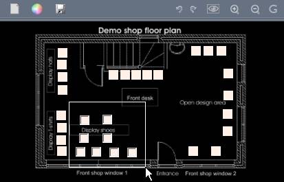
Layout:
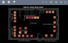
The layout is a 2D representation of your installation allowing you to
easily select and move the position of your fixtures and add backgrounds.
Fixture properties:
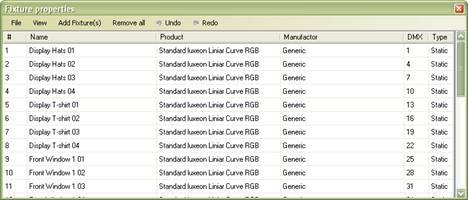
Each fixture has parameters such as name, data DMX address and colour
profile ensuring that the fixture always outputs the correct colours.
Designs saved on device presets

Each preset on your device contains a design, which can be static or
contain a shifting colour show.
As the project is saved in your device, it is always easy to modify an
installation without the need to have the corresponding project file with you.
It is however, recommended to have a backup on file.
Note: A project file does not contain your design library these are
saved locally on your computer.
Note: The background image is not saved in the VX01 device due to space
restrictions. If it is connected to another computer that does not have the
background image stored, it will not be shown.
2
Connection
2.1Connecting USB device
Important! The vDesigner
must be installed before connecting any device to the USB, or you might risk
the wrong drivers being loaded.
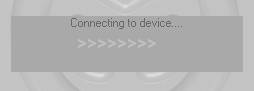
To connect a device to vDesigner, first open vDesigner and then connect
your device to the USB, wait approximately 5 seconds and vDesigner will start
connecting to the device.
When the device has connected the following dialog will appear asking if
you would like to load project from device.
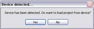
If you choose YES the following dialog will ask you if you want to
override the current loaded project in vDesigner:
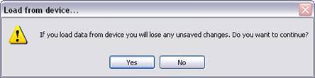
If you have a project loaded that you don’t want to be overwritten choose
NO and you can then save your current project to your hard drive by selecting
File->Save As.
After you have saved the current project you can then load it from the
device again by selecting File->Load Project From Device.
2.2Live output via device
If you have your lighting fixtures connected to your device and your
device connected to your PC while you are working with vDesigner, you will get
a live output of what you’re doing shown on your fixtures.
This can be an advantage as you can accurately see in real life and real
time just how the different designs will correspond with the installation. It
also allows you to quick and easily shows a customer different colour designs
in real life before saving the preset onto the device.
A connection diagram can be seen below.
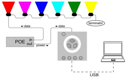
For more detailed information please refer to the installation manual.
3
Setup
3.1Layout
3.1.1
Making
new layout
To make a new layout right click on the Layout Window and select Delete,
this will delete all fixtures if none are selected or if you have selected all.
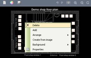
To remove any background picture right click again and select
Background->Remove.
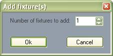
To add new fixtures just click on the Add Fixture(s) button or right click and
select Add.
3.1.2
Zoom
(View size)
You can change the current view size of your layout by using the Zoom In (Picture zoom in) and Zoom Out (Picture zoom out) buttons.
The zoom to fit button (Picture zoom to fit) allows you to quickly set
the zoom and position of the layout to the centre and at an optimal size.
3.1.3
Selecting
fixtures
To select fixtures in the layout simply click on the desired fixture
icon and the fixture is selected.
You can also select multiple fixtures by holding the CRTL Button down and then selecting and
de-selecting the fixtures individually.
Another way of selecting multiple fixtures can be done by making a lasso
around the fixtures you want to select. Start by holding the left mouse button
down outside a fixture icon and the move the mouse to create a lasso around the
fixtures you want to select. When all the required fixtures are surrounded,
release the mouse button and the selection is done.
To deselect all fixtures just click outside the fixture icons.
3.1.4
Adding
background image
To add a background image to you layout, first zoom to the desired size
of your fixture icon(s), then right click on the Layout and choose Background->From
File. Then choose the image you would like to use as background.
The background image is then added in a size as-large-as-possible for
the current zoom.
3.1.5
Moving
fixture icons
The fixture icons can be placed in your layout to make a physical
representation of your installation.
To move your fixture icons simply select one or more fixtures and then
hold the left mouse button down on one of the selected fixture icon and drag by
moving the mouse. When finished release the mouse button.
The zoom can be used to reduce the size of your fixture icons and
thereby giving you more space to place you fixtures.
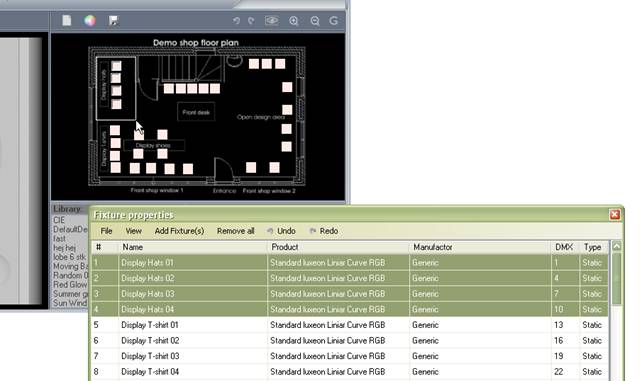
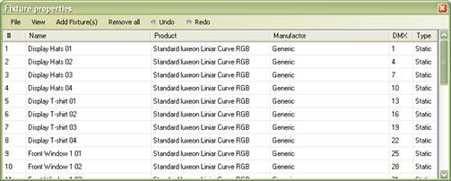
3.2Fixture properties
The fixture properties can be displayed by either: selecting Setup->Fixture Properties or by
right clicking in the Layout Window
and selecting Properties.
3.2.1
What
is DMX?
DMX is the name of the communication protocol used to transmit data
between the control device and the lighting fixtures. DMX is a one way
communication protocol so before an individual fixture can be controlled by the
device both device and lighting fixture(s) need to have a unique address set,
also called a DMX address.
A DMX line (also called “a DMX link” or “a DMX universe”) transmits 512
individual channels. Each of the 512 channels can be set to a value
representing an intensity value from 0% to 100%.
A normal white light would take 1 channel so therefore 512 individual
white light sources could be control on a DMX line independent from each other.
An RGB light uses 3 channels - one for each colour – and therefore up 170 could
be controlled independently on a DMX line and an RGBW uses 4 channels and so
forth.
The DMX address of a fixture must be therefore set depending on how many
channels the other fixtures connected will use, as show below:
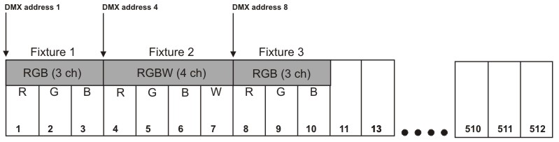
The DMX address is therefore also often referred to a the DMX offset as
it actually is an offset which specifies from which DMX channel the fixture
should start reading channel values.
So if 2 fixtures are set to the same address they will receive the same
values and therefore behave identically if they are the same type.
3.2.2
Selecting
fixtures
To select fixtures in the fixture properties window simply click on the
desired fixture.
You can also select multiple fixtures by holding the ctrl button down
and then select and de-select the fixtures individually.
Another way of selecting multiple fixtures is simply be done by holding
the left mouse button down and then move it down across the fixtures you whish
to select.
To select all fixtures simply right click in the fixture properties
window and choose Select all.
You can also select fixtures in your layout window while the Fixture
properties window is open, as it might be easier for identifying the fixture
you want to select in you layout window.
3.2.3
Naming
fixture(s)
To give a fixture a name simply click on the fixture you want to rename
in the Name column, and type in desired the name.
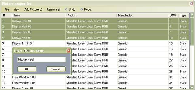
If you want to rename multiple fixtures simply select a range of
fixture, then right click in the Fixture
Properties Window and select Rename
and then type in the name desired. Fixtures are then automatically given the
name followed by an increasing number.
3.2.4
Giving
a fixture a profile
The vDesigner offers a unique colour matching feature to make your work
easier and your designs independent from whatever fixtures you are using or
might be using subsequently.
As most colour changing fixture types are often different in they way
they need to be controlled, in order to create the same colour in each, a
colour profile must be specified for each fixture type. Then the vDesigner and
the device will know how to control the various fixtures in order to ensure the
colour output is the same across different fixture types.
If you have already added some fixtures you will need to give them a
profile. Just select the fixture(s) then right click in the Fixture Properties Window and select Fixture Profiles->Set Profile. The Profile Selector Window will then
appear. First select the Manufacturer of the fixture and then the name of the
fixture then click OK.
You can also add new fixture(s) profiles by using the Add Fixture(s) Menu on the top of the Fixture Properties and then select Add From Profile.
If you cannot find the profile for a specific fixture, the Fixture profile builder can be used to
create your own profile. Please read the
following chapter on how to use the profile builder. For special profiles for
more complex fixture types, please contact you local dealer for more
information.
3.2.5
Fixture
profile builder
The Fixture profile builder can be used to create your own fixture
profiles. The Fixture profile builder can be access in the profile selector by
clicking in the Top Menu and
selecting Advanced and then Create Fixture Profile.
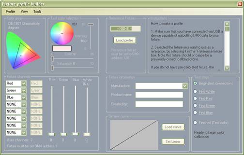
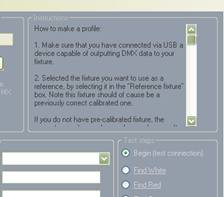
On the right side of the profile builder are instructions shown on how
to create a profile.
When you have added new profiles in your Fixture Profiles Selector they are saved under USER PROFILES.
3.2.6
Setting
DMX addresses
When you have given all your fixtures a profile you will you need to
give your fixtures a DMX address.
You can specify an individual address for each fixture by clicking on a
fixture in the DMX field and then typing in the address manually.
The easiest way to set one or multiple DMX addresses is to select All or
the desired fixtures, and then right clicking in the Fixture Properties Window and selecting Set DMX and then From First
Available. The vDesigner will then automatically address your fixtures.
If you want to re-address all fixtures then first select all fixtures
and then right click in the Fixture
Properties Window and then select Set
DMX -> Clear and then right click again and select Set DMX -> From First Available.
Addresses can also be set starting from specific address by right
clicking and selecting Set DMX ->
From.
When you have set all the DMX addresses you can print out a DMX address
plan that can be passed onto the installer so he know which address the
different fixtures should be set to when making the physical installation. This
can be easily done through the File
Menu.
In the file menu you can also load fixture properties from another
project if desired.
Note: DMX addresses must be set on every fixture to match the addresses
in the Fixture Properties Window.
Addresses are normally set on the fixtures themselves physically using dip
switches or displays, or on the power ballast, while other fixtures are addressed
using special software tools. Please refer to the installation documentation of
the fixtures used for further details.
4
Changing
preset on device
This chapter describes how to add new presets to your device. Before
continuing please read the chapter called; Connection.
Changing presets on your device can be done very simple. First connect
your device to vDesigner using the USB.
When your device is connected choose YES to load a project from the device.
Selecting preset on the virtual device will give you a preview of what
is currently stored in the device.
Note: If you have previously made a colour or speed manipulation of the
preset on the device, then these manipulations are not shown. Only the
originally designs on the preset are shown.
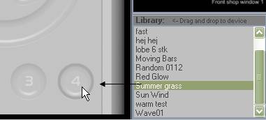
You can now select and preview different designs in the design library.
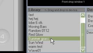
When you have found a design you like, simply drag and drop it onto the
desired preset button on the virtual device.
When you have finished changing the preset as desired, click on the File Menu and select Save Project to Device. The changes are
now stored in the device and ready to be used.
5
Making
your own designs
This chapter describes how to create your own design. You should read
the chapter Setup->Layout->Selecting
Fixtures before continuing.
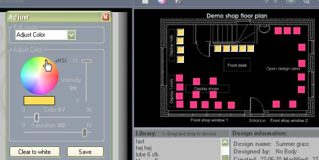
5.1The colour selector
The colour selector is the tool used to change or set a specific colour
when creating or modifying designs.
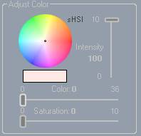
The colour selector is very simple to work with. The standard colour
model is HIS, which stands for Hue (also called colour), Saturation (how deep
or faint that colour is) and Intensity (how bright the colour is).
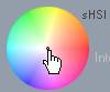
To select a colour, you can simply select the colour directly by
clicking on the round colour circle:
Or by using the 3 sliders:
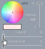
If you wish to make small or finer adjustment to the slider values
simply click on a slider and use the arrow keys to make the adjustments.
You can also select RGB colour control by clicking on the HSI label.
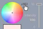
(RGB colours are colours created from the mixture of Red, Green and
Blue).
Note: Using RGB does not mean that if the fixtures connected are using
an RGB colour mixing system you can control the 3 colour values in the fixture
directly. It instead depends on the colour profiles of the fixture, so setting
Red to full might not make an LED fixture glow Red for example, if Green and
Blue are also present.
5.2Creating a scene
A scene is also called a static look, meaning a non colour-changing
design.
5.2.1
Manually
To create a static colour-design simply click on the Edit Button, to open the Editor.
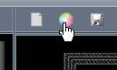
If you have another static or dynamic design running you can clear it
out so you have an empty design by clicking on the Clear Icon.
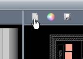
Or on the Clear Button in the
Colour Edit Window.
When no fixture is selected and you select a colour, the same colour
will be set on all fixtures. If you want to set a colour on certain fixtures
simply select the fixtures in your layout and then set the desired colour for
those.
5.2.2
Using
an image
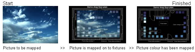
Another possibility is to create a scene from an image, meaning that if
you have an image that has a desired colour scheme it can be transferred to
your fixtures. (This is also known as Pixel Mapping).
vDesigner creates a scene from an image by placing the image on top of
your layout and sets the fixtures to correspond with the colours where the
individual fixture correlates with the image as shown below:
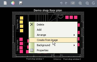
To create a scene from and image, simply right click in the Layout Window and select
Create From Image.
Then select the image you would like to use in the browser and the
picture is transferred to you fixtures. This way of creating a scene can save
you a lot of time as a scene with multiple colours can be created in the matter
of seconds.
5.3Creating a timeline
5.3.1
What
is a timeline?
A timeline consist of multiple scenes and is also called a sequence of
scenes. You can make the timeline step from scene to scene thus creating a
design where colours are changing over time.
Imagine that a scene is a picture, when you have more pictures you can
then create a slide show, how fast the pictures (scenes) should change can be
adjusted in the timeline until you have your desired colour changing design.
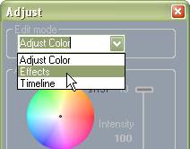
5.3.2
Opening
the timeline window
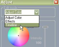
To open the timeline window simply click on the Edit Button.
Change the edit mode to Timeline
by select it using the drop down menu.
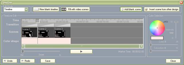
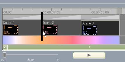
5.3.3
Creating
a simple timeline
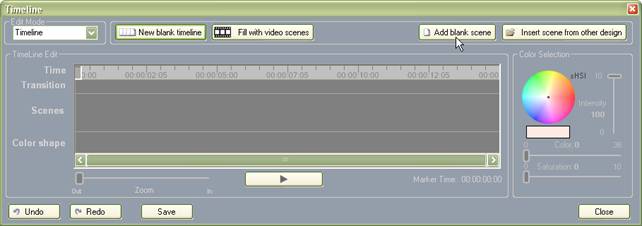
Before you start creating a new timeline you need to clear it of any
other timelines which may have been loaded. To clear your timeline simply click
on the button New Blank Timeline or
on the Clear Icon on top of the Layout Window.

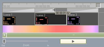
To add a new scene simply click on the button on top of the timeline
called Add Blank Scene, a scene will
now appear on you timeline.
Click on the Add Blank Scene
button an additional 2 times and you have now created a simple timeline
consisting of 3 scenes.
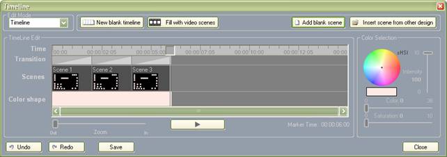
The 3 scenes in the timeline now have the same colour so you now need to
give them an individual colour scheme. This is simply done by selecting each
scene by clicking in the middle of it.
When you have selected a scene simply set the colours of the scene as
described previously in the chapter; Creating a Scene, and using the Colour Selector to the right of the
timeline.
When you have given each scene a colour scheme click on the Play Button.
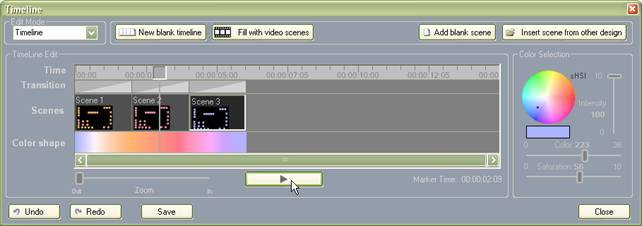
Your timeline will now play back in sequence with the colours changing
over time accordingly to you 3 scenes. You can view this in the Layout Window.
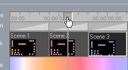
You can pause the playback by clicking the Play Button again. It is also possible to scroll through your
timeline by clicking on the Time
Indicator and moving it manually.
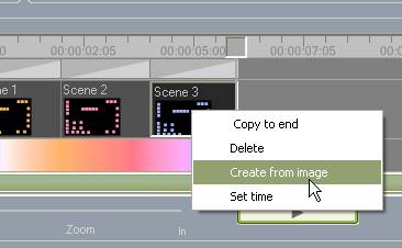
A scene can also be created from an image as described previously in Creating
a scene, just right click on a selected scene and select Create From Image.
Note: The maximum number of scenes allowed in a timeline is 24.
5.3.4
Timeline
view
You can zoom in and scroll your timeline using the zoom slider and the
scroll bar.
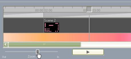
When you zoom in, you will centre in on the location of the timeline
marker, so to zoom in on a specific location just move the timeline marker to
the position you want. Once you have zoomed in you can also use the scroll bar
to scroll through you timeline.
Zooming in on one or more scenes can be necessary for selecting and
adjusting a scene time more accurately.
5.3.5
Deleting
a scene
To delete a scene simply select the scene and push Delete. A scene can also be deleted by right clicking on the scene
and selecting Delete.
To delete all scenes just click on the button New Blank Timeline.
5.3.6
Copy
a scene
To copy a scene right click on it and then select Copy to End. A copy of the scene is then placed at the end of you
timeline and you can then move the scene to the location desired.
5.3.7
Moving
a scene
To move a scene hold the left mouse button down in the middle of the
scene and then drag the scene to where you want it moved.
Note: Make sure that you click in the middle of the scene and not on the
side because you might reset timings. If necessary zoom in to make the
selection easier.
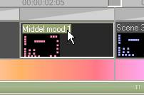
5.3.8
Naming
a scene
You can give each scene a name to making it easier to navigate your
design. To give you scene a new name just click on the scene text and type in a
new name.
5.3.9
Copy
a scene from other timeline
If a design or timeline contains one or more scene you would like to use
in another timeline, you can copy it to your timeline to avoid recreating them.
To do this, click on the button Insert
Scene From Other Design and a window will now open showing you the timeline
of other designs.
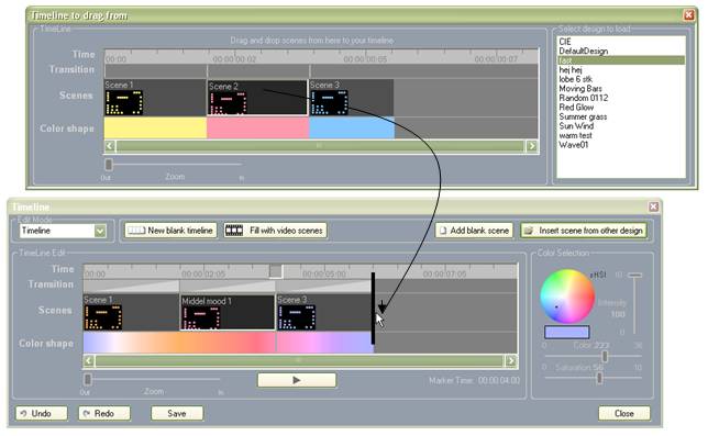
On the right side of timeline viewer you can select the timeline you
want to load. Then hold your mouse down on the scene you want to copy and drag
it to you timeline. The scene has now been copied.
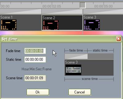
5.3.10
Timing
settings of scenes
Scene time
When scenes are added to your timeline they are given a scene time of 2
seconds by default. If you wish to shorten or extend this time, simply move
your mouse to the right side of the scene and then hold the left mouse button
down. You can now adjust the scene time.
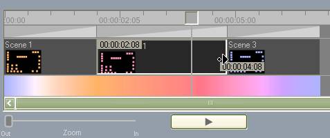
The two time indicators show the time of the selected scene you are
adjusting and the absolute time from the beginning of you timeline to the end.
It is also possible to adjust the time between two scenes without
changing the total time of the timeline. To do this, move your mouse to the
left side of the scene and then hold down the left mouse button.
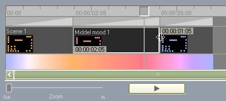
The scene time of the scene selected and the previous scene can be
viewed in the time indicators.
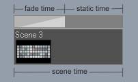
Fade time
A scene consists of two times the Scene Time and the Fade Time. By
default the Fade Time and Scene Time are identical - meaning a scene will be
faded in during the whole scene time. The illustration below illustrates the
two times more clearly.
You might want to adjust your fade time if you want a scene to be faded
more quickly in and stay static for the remaining scene time.
The fade time is represented above every scene by a cross triangle Fade Block. To adjust the fade time
simple move your mouse to the right side of the Fade Block and hold the left mouse button down and then move the
mouse.
The fade time can also be typed in directly by right clicking on a scene
and selecting Set Time.
5.3.11
Adding
video to timeline
As explained previously is it possible to create a scene from an image
and the same is possible with video.
Adding video to your timeline is done by clicking on the button Fill With Video Scenes

Then select a video file in the browser.
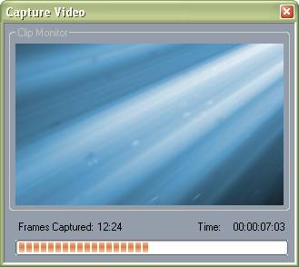
The vDesigner will now split the video up into a series of images and
add them to you timeline, just like when you created scenes from an image.
The number of scenes created depends on how much space is left in the
timeline. As explained previously a timeline can have a maximum of 24 scenes,
so if there are no other scenes present, 24 individual scenes will be made with
timing set according to the video.
This method of creating a timeline gives you the possibility of creating
a colour changing look in seconds that might otherwise have taken much longer.
5.4Creating a colour effect
5.4.1
What
is a colour effect?
A colour effect is a method that allows you to easily create a colour
changing design. Maybe you need to create a design where colours move from one
side to another or patterns changes from circular to square etc. In such cases
it is you will need to use a Colour
Effect Generator.
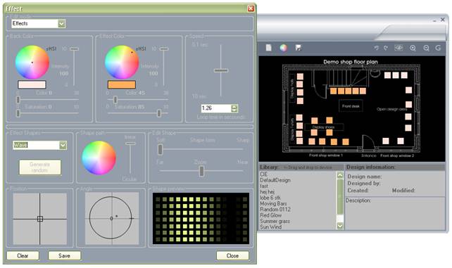
To open, click on the Edit Button
Then select the edit mode; Effects
in the Edit mode drop down menu.
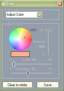
5.4.2
Selecting
effect colours
The effect edit uses two colours called Back Colour and Effect
Colour.
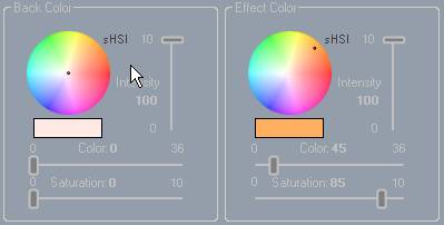
The Back Colour is the basic background colour of the effect while the
Effect Colour is the colour that you want applied to your effect.
Both colours can be adjusted using the standard colour selector as
previously described.
5.4.3
Creating
a simple wave effect
When you click on the Clear
Button all the effect controls are set to default, which creates a simple
wave effect.
To change the colours of the effect, simply change the Effect Colour and preview the effect in
the layout window.
The Shape Preview Window
shows the type of shape of the effect without colours.
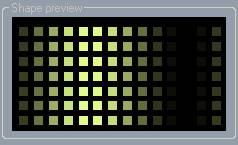
It can sometimes be difficult to identify what kind of effect you have
created if you have a low number of fixtures, so in the Layout Window the Shape
Preview gives you a clear example of the effect.
5.4.4
Effect
speed
The effect speed can easily be changed by using the effect speed slider.
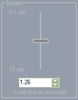
Or the effect loop time can be typed directly in to the box below the
slider.
5.4.5
Edit
shapes
In the Edit Shape Window the Shape Form and Zoom Slider can be used to change the properties of the effect.
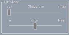
Shape form
The Shape Form Slider makes
it possible select how sharp or soft an effect can be. The illustration below
shows how to adjust the shape form of an effect.
Zoom
The Zoom Slider makes it
possible to zoom in and out of an effect as illustrated below.
If the Zoom Slider is set to Far, all the lights will have the same
effect.
5.4.6
Effect
shapes
The effect shapes can be changed using the drop down menu in the Effect Shapes Panel.
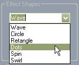
You can chose between the following effects:
Wave
Circle
Rectangle
Dots
Spin
Swirl
It is also possible to create randomized effect shapes by clicking on
the Generate Random button. Every
time the button is clicked the effect is re-randomized.
![]()
5.4.7
Effect
angle
If you have a wave effect for example, the direction of the effect
movement can be changed by using the Angle
Tool.
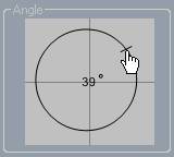
To change the direction of the effect simply click on the Angle Ring and then hold down the left
mouse button and move the mouse to change direction.
Note: If you want to make a finer adjustment of the angle, keep the left
mouse button held down and move the mouse outside the windows.
5.4.8
Effect
position
The position of an effect can be changed to create a new desired look.
(Position will not have any affect on a wave effect as it has no absolute
position point). If you select the effect shape called circle, you can change
its centre position.
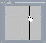
To change the position of the effect move the mouse to the centre point
of the position selector and hold down the left button and move the mouse to
the desired position.
5.4.9
Shape
path
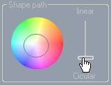
The Shape Path Panel makes it
possible to change the path of how colours go from Back Colour to Effect Colour.
Normally the colour would go in straight line as show below.

But if you want a more colourful effect you will need to move through
more colours when going from Back Colour
to Effect Colour, and this can be
achieved by changing the shape path from linear to circular. To achieve this,
move the Path Slider.
5.5Saving designs
Saving a design can be done by either clicking on the Save Button or by clicking on the Save Icon on top of the Layout Window.
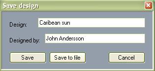
Type in the name of the design and your name if desired, and the design
will be saved to your design library.
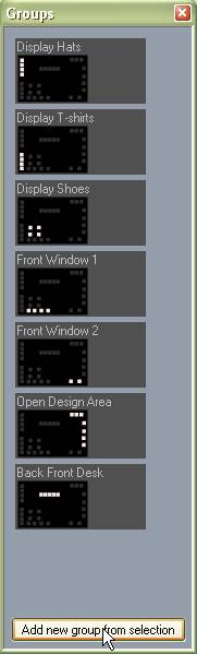
6
Groups
Groups is a tool that
makes it easier to select a frequently selected group of lights. For example if
you have a group of lights that illuminates a front wall and another group of
lights that illuminates a back wall, you might want to create a Group for
selecting the whole back wall by pushing just one button.
This will save you time when creating designs where you often select
certain groups.
To open the group window click on the Group Icon on top of the Layout
Window.
6.1Creating a group
To create a group, first select the fixtures in your layout window that
you want to be included in the group, and then click on the button; Add New Group From Selection. The group
has now been created.
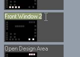
6.2Naming a group
To give your group a name just click on the group text and type in a
name.
6.3Deleting a group
To delete a group right click on the group and select Delete.
7
Security
To open the security setting of the device, click on Setup and then click on Security.
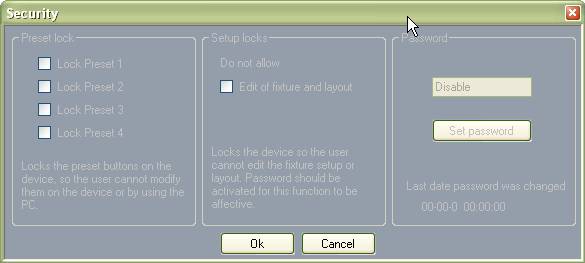
7.1Locking presets on device
The presets on the device can be locked by marking them on the Preset Lock Panel.
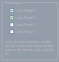
When a preset is locked the user will not be able to change it on the
device and instead will get a; “OHOOHH” acoustic
feedback, indicating that the preset is locked.
Note: The user can still change the preset if the device is connected to
the computer using vDesigner.
7.2Locking layout
Locking the layout prevents the user from changing either the layout or
fixture properties. The lock is enabled by selecting the Edit of Fixture and Layout.
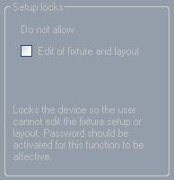
For this function to be affective a password should be enabled.
7.3Password protected
The locked functions can be password protected to ensure that none of
the layouts can be accessed or changed without a password.
The password is enabled by clicking on the Set Password button
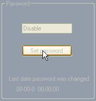
The password can be disabled by changing the password to no characters.
7.4Saving security settings in device
The security settings are saved in the device the next time you save the
project to the device.